Directives Compliance
S-Keeper 7™ has been engineered according to the applicable Directives & Guidelines. Every single detail has been designed to comply with the most up-to-date International Norms as listed in Directives Section. Where multiple potential choices exist, the S-Keeper 7™ engineering team has always preferred to minimize maintenance on-board or to increase the system’s life span.
We suggest downloading the documents listed to check each individual point.
Resolution MEPC. 259(68) 2015 Guidelines for exhaust gas cleaning systems EGCS/Scrubber
This resolution focuses on Sulphur-based pollutants produced after having burnt fuel oil with a certain Sulphur content. As per Regulation 14 Annex VI, a cleaner fuel oil is required to fulfill this requirement and the Shipowner will be well aware of the cost differences between different fuel grades.
Fortunately, Regulation 4 of Annex VI allows the use of the Alternative Compliance Method to match those requirements; for example, an EGC Emission Gas Cleaning system could be installed downstream of the engine to reduce the Sulphur content mitigating the environmental effect.
How can the Shipowner assess the efficiency of the new EGC system just installed on board? How can the EGC be validated? In order to simplify this monitoring, the Guidelines suggest summarizing the combustion phenomena by measuring the SO2 [ppm] / CO2 [% v/v] ratio vs Fuel Oil Sulphur Content [% m/m].
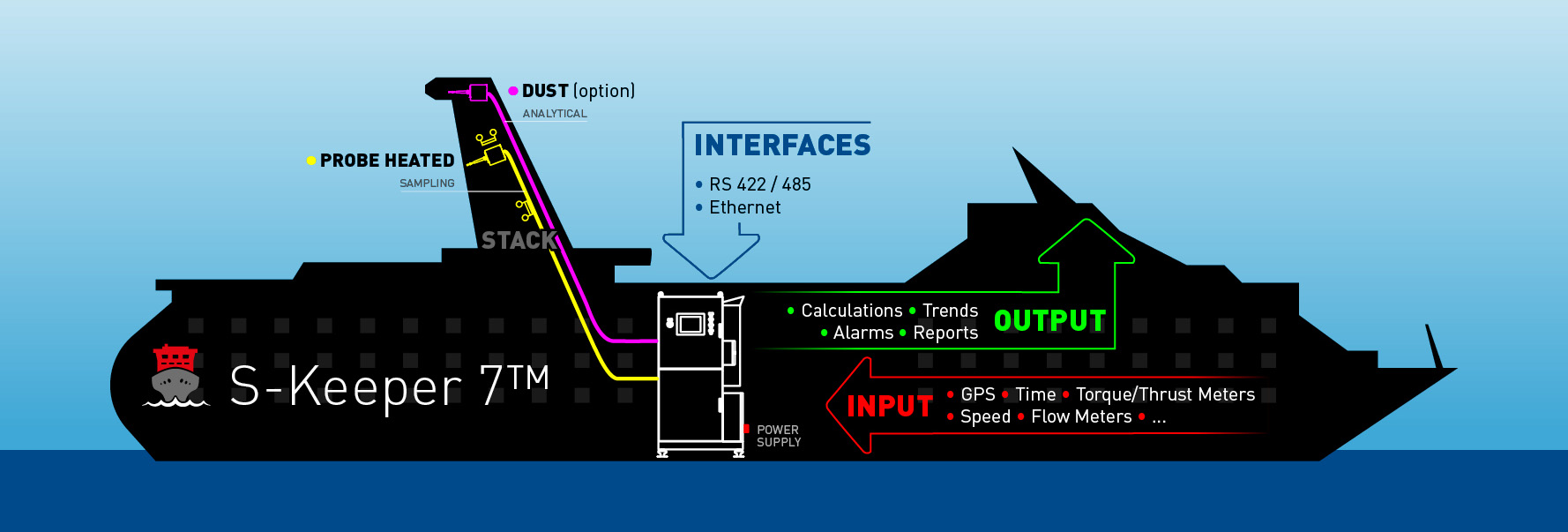
Chapter 6 Emission Testing
As stated in par. 6.1 the Guidelines require Chapter 5 & Appendices of NOx Technical Code 2008 to be followed, but any specific additional requirement must be clarified. The S-Keeper 7™ system is fully compliant with above NOx Technical Code 2008.
In par. 6.2 the CO2 parameter analysis is required to be performed in “dry” mode by a NDIR analyser, such as the ZPA installed in the S-Keeper 7™ system. On the other hand, the SO2 could be measured in both “dry” and “wet” mode by same NDIR or alternative NDUV analyser. In S-Keeper 7™ the SO2 is analysed in “dry” mode to avoid the conversion of SO2 & water into H2SO4 in the event of “wet” mode, leading to corrosion phenomena. A dedicated configuration of the installed cooler prevents any SO2 loss after cooling down, see par. 6.7 .
The analyser performance is assessed as required in Appendix 3 of NOX Technical Code Section 1.6 – 1.10 [par. 6.3] while the Extractive Sampling Method is suggested in par. 6.5 .
Chapter 7 Data Recording and Processing Device
The S-Keeper 7™ built-in software is fully compliant with Chapter 7 thanks to following features vs Chapter 7 paragraphs:
[par. 7.1] S-Keeper 7™ software and relevant hardware was engineered for marine severe conditions so a genuinely industrial computer was selected, in a IP65 housing, fanless and equipped with a solid state disk to avoid any moving parts. Up to 5 different password-protected levels allow different skilled technicians to operate with different responsibilities.
[par. 7.2] Thanks to S-Keeper 7™ multi-input software, the pollutant concentration and EGC parameters are continuously recorded against UTC & GNSS data for evaluation of the time and geographical position: as indicated in par. 7.4 the minimum guaranteed recording span will be 18 months. The system software is also able to prepare full reports in a specified time span [par. 7.3] and to allow them to be downloaded in a user-friendly format suitable for port State authorities [par. 7.5].
Appendix II – Proof of SO2/CO2 ratio method
In this Appendix we clarify the technical background supporting the validity of this ratio to assess the quality of the burnt fuel oil.
The S-Keeper 7™ software is able to measure the above ratio calculating the original Sulphur content in burnt fuel oil and then assessing the quality of the purchased oil; in fact a lower quality fuel oil will lead to a higher SO2/CO2 ratio.
Regulation (EU) 2015/757 – On the monitoring, reporting and verification of carbon dioxide emissions from maritime transport aka MRV
– Annex I “Methods for monitoring CO2 emissions” Method C & Method D
Method C: Flow meters for applicable combustion processes This method is based on measured fuel flows on-board. The data from all flow meters linked to relevant CO2 emission sources shall be combined to determine all fuel consumption for a specific period.
Method D: Direct CO2 emissions measurement The direct CO2 emissions measurements may be used for voyages and for CO2 emissions occurring in ports located in a Member State’s jurisdiction.
Resolution MEPC.177(58) – Amendments to the Technical Code on control of Emission of Nitrogen Oxides from Marine Diesel Engine aka NOx Technical Code 2008
Chapter 5 – Procedures for NOx emission measurements on a test bed
– par. 5.5 Determination of exhaust gas flow
The Exhaust gas flowrate needs to be assessed in order to calculate the mass of pollutants at a given concentration. Three different methods are permitted under the Technical Code:
Direct Mass Flow metering is attractive but according to our field experience it yields poor and unreliable results due to presence of water droplets, an unpredictable velocity profile and high temperatures; moreover, in order not affect the combustion in the engine, there should be no permanent headloss.
The Air and Fuel measurement method is based on mass material balance inlet vs outlet the engine system, thus the air volumetric flow should be normalized in terms of pressure, temperature and humidity while the fuel is either already mass-metered or should be compensated in density.
The Carbon Balance method is based on consumption of a known composition of fuel oil and the concentration of pollutants. The consumption is metered by flowmeters while the fuel composition is given in accordance with ISO 8178 by the bunker vendor. The analysis of each component is performed by a ZPA installed in S-Keeper 7™ together with a FID device which calculates the HC hydrocarbons value. The main formula to be used in this method is described in Appendix 6 – par. 2 of same Resolution.
The third method or “Carbon Balance” is the one selected for S-Keeper 7™, due to its greater overall accuracy and the fact that it does not require additional metering air flow and the related annual validation.
– par. 5.11 Data evaluation for gaseous emissions
In this par. the S-Keeper 7™ software
- will calculate the average concentration of each component on a 60 second cycle
- will display the data by percentage in the case of O2 and CO2 to 2 decimal places XX,YY and by ppm for the other components
– par. 5.12 Calculation of gas emissions
In this par. the S-Keeper 7™ software will perform in real time
- Determination of exhaust Mass flow
- Dry/Wet Correction for all pollutants but NOx
- Dry/Wet Correction for Intake Air
- NOx correction for intake air Temperature & Humidity
Then the S-Keeper 7™ software will calculate
- Emission Mass Flow Rate for each pollutant [g/hr]
Finally S-Keeper 7™ will process the engine power kW together with engine rpm to estimate the
- Specific Emission for each pollutant [g/kWh]
Then, in accordance with Annex VI Regulation 13 and the Ship applicable TIER Limit, the S-Keeper 7™ software will assess the conformity of NOX emission value.
Chapter 6 – Procedures for demonstrating compliance with NOx emission limits on board
This chapter focuses on achieving compliance regarding NOx emission limits for a pre-certified engine (EIAPP certified) installed on board. Three validation methods are listed and usually the Engine Manufacturer specifies one of them. However, according to par. 2.4.5 of NOx Technical Code , the ShipOwner shall have the option of Direct Measurement of NOx emissions in accordance with par. 6.4, in order to provide an independent and unbiased validation of the purchased engine.
– Par. 6.2 Engine Parameter Check method
This method is based on a large database of performance data collected by the Engine Manufacturer. The method, which has fixed side process parameters, infers the expected NOx value on board.
Pros
- No exhaust gas measurement system required at all
- Additional sensors out the Engine Manufacturer’s usual supply are not necessary for the validation
Cons
- Not suitable for older engines not yet designed to be compliant with NOx limit
- Large set of parameters to be collected and reported as per 6.2.2.7 leading to huge time consumption
- Any engine modification, even minimal, should be properly recorded
- Sailing in ECA will require continuous parameter monitoring to asses NOx limit in accordance with Regulation 13 to avoid fines.
- Any real time modification of ship cruising parameters such as speed to stay within the required limit, is very difficult if not impossible.
– Para 6.3 Simplified Measurement method
This method is based on spot analysis performed by the service team using portable device. After having climbed up the ship stack, the dedicated personnel insert the sampling probe into a dedicated nozzle: the sample is sucked inside the analytical box and the pollutants evaluated.
Pros
- A simplified, and therefore less expensive, portable exhaust gas measurement system is required
Cons
- Large set of parameters to be collected and reported as per 6.2.2.7 leading to huge time consumption
- Specific training for sampling is needed for each Operator to achieve an acceptable repeatability
- Sailing in ECA will require continuous parameter monitoring to asses NOx limit in accordance with Regulation 13, to avoid fines.
- Periodic manual validation required to assess accuracy & repeatability of portable device
– Par. 6.4 Direct Measurement and Monitoring
This method is based on an integrated analysis system in compliance with Appendix 3 of this Technical Code equipped with a heated line for sample extraction and calibration bottles and supervised by specific software to perform the calculations, trends and reports.
Pros
- Real time measurement and recording of exhaust emission during ship cruising
- During ECA cruising NOx limit Regulation 13 conformity self-assessed via software
- Sampling & Conditioning of exhaust gas fully compliant with NOx Technical Code
- Auto Calibration & Validation to be in conformance with NOx Technical Code
- Automatic collection of necessary ship parameters in accordance with table 7 par. 6.4.3.1 and table 8 par. 6.4.4.1 as shown on NOx Technical Code
- Additional inputs to achieve better ship efficiency such as thrust & torque, fuel flow metering…
Cons
- Higher initial cost than first & second methods
- Footprint to be considered especially for retrofitting
S-Keeper 7™ is in compliance with the above par. 6.4 Direct Measurement & Monitoring Method and engineered in accordance with Appendix 3 of NOx Technical Code. This choice was made in order to turn the cost of the system into a long-term investment, engineering the S-Keeper 7™ as a smart-hub aggregating several data offering the solution for truly Green Efficiency on Board.
Appendix 3: Specifications for analysers to be used in the determination of gaseous components of marine diesel engine emissions
The pneumatic section of S-Keeper 7™ has been designed in accordance with par. 1.1 so the sample must be extracted and carried from stack to analyser cabinet. Provision of heated line is necessary to avoid any condensation, including that of acid. The advantage for the Shipowner is easier maintenance because the most critical item of the system, the analyser, is not exposed to tough process conditions or severe ambient conditions such as high temperature or vibrations. At same time the Service team will work more safely and easily because the S-Keeper 7™ sample probe, installed in situ, is maintenance-free.
As soon as the sample is carried inside the cabinet is split into 3 independent lines: 2 of them are dedicated to NOx, CO2, CO, O2 [together with SO2 in accordance with Resolution MEPC.259(68) 2015 Guidelines for exhaust gas cleaning systems] while the remaining one is specific to HC Hydrocarbons.
According to par. 1.2.8 a NDIR Non Dispersive InfraRed measurement method is indicated for analysis of the CO & CO2, and consequently the integrated analyser ZPA model is fully in compliance with this requirement.
To detect HC Hydrocarbons content par. 1.2.9 indicates the HFID Heated Flame Ionization Detector and consequently the integrated analyser ThermoFid SK7 was selected.
The NOx parameter according to par. 1.2.10 could be measured by CLD ChemiLuminescent Detector technology. Based on its extensive field experience, S – Keeper 7 engineering team has again preferred the NDIR technology of the ZPA model, for several technical reasons: it is absolutely much more robust due to a simpler internal configuration, and consequently it has the mandatory repeatability for this tough marine installation. This upgrading of technology was permitted since the accuracy/precision/span drift/…features match those of the CLD analyser, as shown in the Equivalent Test in accordance with par. 5.4.2 of same Resolution MEPC.177(58).
Of the 3 potential principles of measurement dedicated to O2 (Paramagnetic, Zirconium Dioxide, Electrochemical sensors) as indicated in par. 1.2.12, after careful deliberation the S-Keeper 7™ engineering team selected the Zirconium Dioxide method used in ZFK7 analyser: this method has been used in hundreds of thousands of field installations and is virtually maintenance free, with no moving parts, a robust design and an extended lifetime so that ownership costs are kept to a minimum.
As stated in par. 1.2.11, NO2 conversion to NO is required by means of a CRC Catalytic Reduction Converter upstream the ZPA analyser: the ZDL04 was selected due its numerous good references, minimal footprint and faultless conversion rate.
The proven quality of S-Keeper 7™ system is also a result of the careful choice of each component. For example, the Cooling Unit, responsible for reducing the gas temperature to 0°C, was totally redesigned to deal the challenging ambient conditions of marine indoor installation and vibrations issue: the core is a Peltier cooler instead of a standard compressor while the exchange area was upgraded to achieve a higher efficiency suitable for high temperature. Par. 1.2.13 indicates the operating range of this device.
Appendix 4 – Calibration of the analytical and measurement instruments
This appendix deals with the following procedures:
– par. 2.1 Pure Gases including Zero Check Gas
A H2/He bottle is required to feed the FID analyser: this requirement leads to huge consumption of gas and consequently the need to store of H2 bottles on board, but this strategy could unfortunately jeopardize the ship’s safety and increase the ownership cost.
S-Keeper 7™ was engineered to self-produce the required H2 flowrate without the need for any bottle or similar device.
-par. 2.2 Calibration and Span Gas
A single component bottle is required (CO in N2, CO2 in N2…) to perform the routine calibration. Based on our field experience the presence of a such a huge quantity of Pressurized Nitrogen could lead to hazardous conditions due to limited space: in the event of the rupture of bottle fittings, the Nitrogen would replace the breathable air within a few seconds. The S-Keeper 7™ system has also taken this potential event into account, selecting a special marine approved version of each pressurized bottle, with low pressure and volume. These special bottles are Single Use and are defined as “disposable” and T-PED certified so that they can be freely carried by truck/ship/airfreight: this will allow the Maintenance Manager to re-stock them easily.
– par. 7 Efficiency Test of NOx Converter
The Technical Code is required for the validation of the efficiency of the converter before any calibration of NO analyser: an ozone generator is required together with a dilution system. Due to high frequency of this validation procedure (3 months minimum), S-Keeper 7™ internal software has been designed to carry out this procedure automatically, including in unmanned mode.